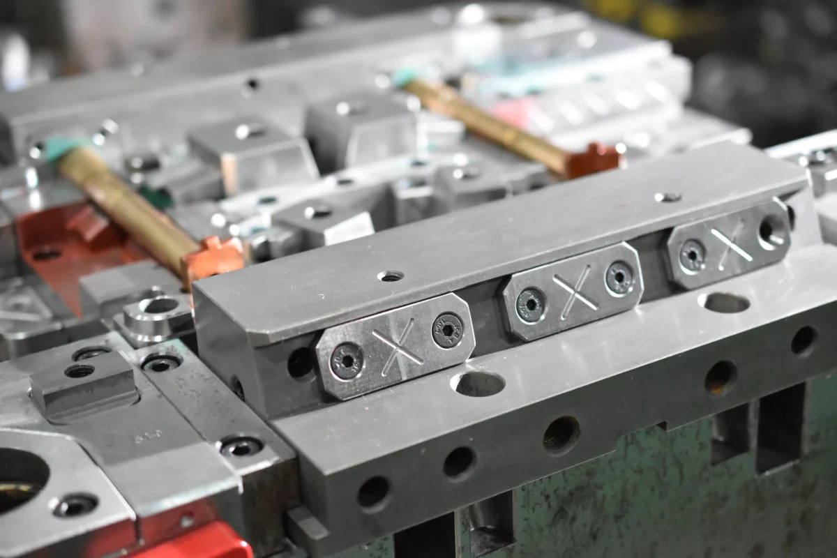
Mold solutions solve injection molding problems by controlling melt flow, cavity pressure, heat removal, air release, shrinkage, and part ejection before production settings are pushed outside a stable range. Cooling commonly occupies more than 50% of an injection molding cycle, so channel layout alone can affect both output and dimensional repeatability. Wall thickness also matters: Protolabs recommends keeping minimum walls at roughly 40–60% of the thickest nearby section where thickness changes cannot be avoided. Material behavior can be equally large; BASF data published in 2025 shows reinforced PA grades with directional molding shrinkage ranging from about 0.20% to 0.90%.
A short shot often appears to be a machine-pressure problem, but increasing injection pressure can mask a restrictive runner, undersized gate, early gate freeze, poor venting, or an unnecessarily long flow path. Pressure is highest near the machine nozzle and falls as polymer passes through the sprue, runner, gate, and cavity, so a thin section near the end of fill may receive much less pressure than the machine display suggests. RJG notes that managing pressure loss throughout the complete melt path is necessary for reducing short shots, sink, warp, and dimensional variation.
For a four-cavity tool, runner imbalance deserves the same attention as machine settings. One cavity can reach the end of fill while another remains partially filled, particularly when flow lengths, gate restrictions, or cooling conditions differ. Raising pressure to fill the slow cavity can then push the first cavity toward flash. A more useful engineering response is to compare fill patterns, gate dimensions, cavity pressure, and part weight cavity by cavity rather than treating four molded parts as one process result.
Air evacuation becomes more important as filling speed rises. The cavity is full of air before every shot, and that air must escape while polymer may fill the cavity in well under 2 seconds on small high-speed parts. Restricted vents can leave brown or black burn marks where compressed gas becomes hot, while insufficient air release can also slow the melt front and contribute to incomplete filling. Protolabs identifies poor venting as one of the mold-related causes of burns, short shots, and surface problems.
Vent dimensions therefore need to match the resin rather than follow one universal number. A vent must be deep enough to release gas but shallow enough to stop molten material from flowing through it. Vent position also matters: end-of-fill regions, weld-line areas, deep ribs, and locations around inserts often need more attention than open areas near the gate. After tens of thousands of cycles, residue from resin, additives, or degradation products can reduce the usable vent opening, which is why accessible vent surfaces make routine mold maintenance easier.
Cooling usually offers the largest opportunity for cycle improvement because it can occupy more than 50% of the complete molding cycle. A 30-second cycle running four cavities produces a theoretical 480 parts per hour. Reducing the cycle to 27 seconds raises theoretical production to 533 parts per hour, an increase of about 11.1%, without increasing cavity count. Cutting time without controlling mold temperature, however, can increase post-ejection movement and dimensional variation.
Faster cooling is not automatically better cooling. A cavity surface that cools one side of a housing much faster than the opposite side can shorten machine time while increasing differential shrinkage.
Straight drilled channels work well when they can remain reasonably close to cavity and core surfaces. Deep cores, tall bosses, curved housings, and closely spaced inserts can leave hot areas that conventional drilling cannot reach. Baffles and bubblers can redirect water into narrow regions, separate circuits can serve areas with different thermal demand, and conformal channels can follow complex mold surfaces where conventional passages leave large temperature differences.
Part geometry has to support that thermal design. Thick material concentrations around bosses, ribs, corners, and mounting features cool more slowly than the nominal wall. As the inner material contracts after the surface has become relatively rigid, the outer face can pull inward and form a sink mark. Protolabs recommends avoiding abrupt wall differences and cites a general guideline in which thinner regions should not fall below roughly 40–60% of the thickest adjoining section.
Ribs illustrate the interaction between part design and mold performance. Making a rib very thick can improve stiffness in CAD while creating a local mass of polymer that requires longer cooling and additional packing. Making it too thin can make filling difficult. Gate placement also affects the result because packing pressure can compensate for material contraction only until the gate freezes. Once frozen, extra hold time at the machine cannot send additional polymer into that region.
Material shrinkage adds another layer. BASF’s 2025 data for Ultramid B3WG10, a glass-fiber-reinforced PA6, lists molding shrinkage around 0.70% normal to flow and 0.20% parallel to flow for one grade. Another reinforced Ultramid grade lists approximately 0.90% normal and 0.30% parallel. Fiber orientation can therefore make shrinkage directional rather than uniform, affecting flatness, hole position, and long dimensions.
| Mold condition | Production symptom | Mold-side response |
|---|---|---|
| Uneven temperature | Bowing, twisting, unstable dimensions | Rebalance cooling circuits and local heat removal |
| Restrictive gate | Short fill, high required pressure | Review gate area, position, and freeze time |
| Poor air release | Burns, hesitation, incomplete fill | Add or relocate vents and maintain vent surfaces |
| Heavy local section | Sink, long cooling time | Reduce material concentration and improve local cooling |
| Unequal cavity flow | Part-to-part variation | Balance runners, gates, venting, and cavity conditions |
Warpage often appears after ejection rather than while the part is still inside the tool. Uniform wall thickness helps because sections with different mass cool and contract at different rates. Glass-reinforced polymers require additional care because fibers tend to align with melt flow. Protolabs notes that filled resins can be more susceptible to warp, while BASF data shows why: one reinforced PA grade has a thermal expansion coefficient of about 15 × 10⁻⁶/K parallel to flow but 73 × 10⁻⁶/K in the normal direction between 23°C and 55°C.
Gate location can change that orientation pattern. Moving a gate may move a weld line, alter filling pressure, change which end of the part packs first, and change fiber direction around holes or ribs. A mold-flow study can help compare proposed gate positions before steel is machined, but simulation inputs must reflect the actual resin grade, melt temperature, mold temperature, gate geometry, and intended machine because approximate inputs can produce approximate predictions.
Weld lines need similar treatment. They form when separated melt fronts move around a hole, insert, boss, or other obstruction and meet again. A visible line may only affect appearance, but placement across a stressed mounting feature can reduce local strength because the two fronts have already lost heat before joining. Protolabs describes weld lines as areas where separated flows meet and notes that the result can range from a visible mark to a structural concern.
Changing gate position may relocate the meeting point to a less demanding area. Improving venting near that meeting point can help displaced air escape, while maintaining sufficient melt temperature and pressure can improve bonding. Adding injection pressure alone is not always useful because additional pressure may create flash elsewhere before it substantially changes the weld-line condition.
Flash itself should be investigated at the mold before repeatedly lowering process settings. Common mold causes include parting-line mismatch, worn shutoffs, damaged inserts, inadequate support, debris between closing surfaces, and vents that are too deep. Protolabs also notes that very thin sections can require higher pressure to fill, increasing the likelihood of flash when mold sealing is marginal. A tool expected to run 1 million cycles needs a different wear and service plan from one intended for 5,000 prototype parts.
Replaceable inserts, wear plates, and serviceable shutoff areas can make that production life easier to manage. Mold steel should also be selected according to resin, glass content, surface requirements, cavity count, and expected shot volume. Glass-filled materials can wear gates and sliding surfaces faster than unfilled grades, while corrosive materials may require steel and surface treatments selected for chemical resistance rather than hardness alone.
Part release is another mold function that can damage an otherwise acceptable molding. Protolabs recommends at least about 0.5° of draft on many vertical walls, notes that 2° is preferable in many cases, and states that heavily textured surfaces may require 5° or more. Exact draft depends on resin, texture depth, wall height, surface finish, and whether the part shrinks tightly around a core.
Ejector placement then has to spread removal force across areas strong enough to receive it. Too few pins can leave deep marks or deform a warm wall; pins placed under unsupported cosmetic surfaces can create visible read-through. Sleeves can support round bosses, stripper systems can spread force over larger areas, and properly placed ejector pins can reduce local stress. Cooling and ejection must be considered together because a part removed 2 seconds earlier may still be too soft to retain its intended geometry.
Tolerance planning should also reflect material data rather than use a single shrinkage allowance across the entire model. BASF’s January 2025 data for an unreinforced PESU grade reports molding shrinkage of about 0.82% parallel to flow and 0.86% normal to flow, while reinforced PA examples can show much larger directional differences. Dimensions near gates, across long flow paths, or around fiber-oriented features may therefore behave differently even within the same component.
Steel-safe dimensions can provide room for controlled adjustment after first trials. Where a feature can be enlarged later by removing steel, the mold can begin slightly conservative and be corrected after measured parts establish actual shrinkage. Trial measurements should be taken only after the molding process reaches stable temperatures and parts receive an appropriate conditioning period; otherwise tool changes may be based on transient dimensions rather than production behavior.
For multi-cavity production, measurement should retain cavity identity. If 32 parts are inspected without recording which of eight cavities produced each part, cavity-specific dimensional patterns disappear into one data set. Recording cavity number, cycle condition, part weight, and selected dimensions makes it easier to separate mold variation from general process movement. RJG also notes that part weight can show that a process has changed but cannot by itself identify whether the cause came from viscosity, temperature, filling, packing, or cavity imbalance.
A mold supplier therefore needs to review more than the CAD geometry. Material datasheets, annual production volume, machine size, required tolerance, cosmetic surfaces, gate restrictions, assembly interfaces, expected tool life, and inspection methods all affect mold construction. Working with an experienced supplier such as Qlution Manufacturing can place DFM review, mold engineering, sampling, dimensional inspection, and production requirements in the same manufacturing workflow before expensive steel changes are required.
Maintenance planning should begin at the same stage. Cooling passages need access for cleaning, vents need surfaces that can be serviced without removing large mold sections, and high-wear components should be replaceable where expected cycle volume supports the added tooling cost. A mold that runs 500,000 cycles with predictable preventive maintenance is easier to schedule than a mold that produces acceptable first samples but requires repeated unscheduled repair.
Production approval should finally be based on a repeatable process window rather than a single acceptable shot. Testing at more than one melt temperature, mold temperature, injection speed, and packing condition can show how close production is to short shot, flash, sink, or dimensional limits. If acceptable parts appear only within a very narrow setting range, small changes in resin lot, ambient conditions, machine response, or mold temperature can move the process outside specification even though the mold passed its first trial.